

Methods for heat dissipation of circuit boards
1. The widely used PCB boards for heat dissipation are copper-clad/epoxy glass cloth substrates or phenolic resin glass cloth substrates, and a few paper-based copper-clad boards are also used. Although these circuit board substrates have excellent electrical and processing functions, their heat dissipation is poor. As a heat dissipation pathway for high heat generating components, it is impossible to rely on the resin of the PCB itself to conduct heat, but rather dissipate heat from the surface of electronic components to the surrounding air.
But as electronic products have entered the era of component miniaturization, high-density devices, and high heat generation assembly, relying solely on the surface area of components to dissipate heat is not enough. At the same time, due to the extensive use of surface device components such as QFP and BGA, a large amount of heat generated by the equipment is transferred to the PCB board. Therefore, the best way to solve the heat dissipation problem is to improve the heat dissipation ability of the PCB itself that directly touches the heating element, and to export or dissipate it through the PCB board.
2. It is best to place integrated circuits (or other equipment) vertically or horizontally when selecting equipment for free convection air cooling.
3. Choosing a reasonable wiring design to achieve heat dissipation is crucial because the resin in the circuit board has poor thermal conductivity, while copper foil lines and holes are good conductors of heat. Therefore, improving the copper foil residual rate and increasing thermal conductivity holes are the primary methods for heat dissipation. To evaluate the heat dissipation capability of PCB, it is necessary to calculate the equivalent thermal conductivity of the insulation substrate used for PCB, which is a composite material composed of various materials with different thermal conductivity coefficients.
4. When there are a few devices in the PCB that generate a large amount of heat (less than 3), a heat sink or heat pipe can be added to the heating device. When the temperature cannot be lowered, a heat sink with a fan can be used to enhance the heat dissipation effect. When the amount of heating equipment is large (more than 3), a large heat dissipation cover (board) can be used, which is a specialized heat sink customized according to the orientation and concave convex of the heating equipment on the PCB board, or different component concave convex orientations can be carved out on a large flat heat sink. Attach the entire heat dissipation cover onto the surface of the component and dissipate heat by touching each component. But due to the poor consistency of the unevenness during the assembly and welding of the equipment, the heat dissipation effect is not good. Usually, a soft thermal phase change thermal pad is added to the surface of the raw material to improve heat dissipation.
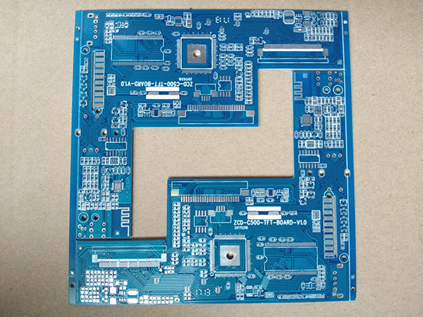
5. Equipment on the same printed circuit board should be placed in different zones according to their heat generation and heat dissipation degree as much as possible. Equipment with low heat generation or poor heat resistance (such as small signal transistors, small-scale integrated circuits, electrolytic capacitors, etc.) should be placed at the top (inlet) of the cooling airflow, while equipment with high heat generation or good heat resistance (such as power transistors, large-scale integrated circuits, etc.) should be placed at the bottom of the cooling airflow.
6. In the horizontal direction, high-power equipment should be placed as close as possible to the edge of the printed circuit board to shorten the heat transfer path; In a straight direction, high-power equipment should be placed as close as possible to the printed circuit board to reduce the impact of these equipment on the temperature of other equipment during operation.
7. The heat dissipation of printed PCB boards in equipment primarily relies on air activity, so in design, it is necessary to study the pathways of air activity and equip equipment or printed circuit boards reasonably. During air activities, there is always a tendency towards local activities with low resistance, so when equipping equipment on printed circuit boards, it is important to avoid leaving large airspace in certain areas. Equipment with multiple printed circuit boards in the entire machine should also pay attention to the same issue.
8. It is best to place equipment that is sensitive to temperature in the area with the lowest temperature (such as the bottom of the equipment), and never place it directly above the heating equipment. Multiple equipment should be interwoven and arranged on a horizontal plane.
9. Place the equipment with the highest power consumption and heat generation in the vicinity of the optimal heat dissipation position. Do not place equipment with high heat generation in the corners and edges of printed circuit boards unless there are heat dissipation devices nearby. When designing power resistors, choose larger equipment as much as possible, and adjust the layout of the printed circuit board to ensure sufficient heat dissipation space
Article source: PCB manufacturerhttp://www.yonghongpcb.com/
-
09-09
Schematic diagram of Jiangmen single and double-sided circuit board
1. There are now various specialized PCB drawing software, such as Protel, which can draw multi-layer (including double-sided) circuit board diagrams. The layers are aligned in orientation and have vi
-
09-09
Schematic diagram of Jiangmen single and double-sided circuit board
1. There are now various specialized PCB drawing software, such as Protel, which can draw multi-layer (including double-sided) circuit board diagrams. The layers are aligned in orientation and have vi
-
09-09
Schematic diagram of Jiangmen single and double-sided circuit board
1. There are now various specialized PCB drawing software, such as Protel, which can draw multi-layer (including double-sided) circuit board diagrams. The layers are aligned in orientation and have vi
-
04-27
What is the structure of blind buried hole circuit board?
blind and buried viascircuit boardIt has the ability to freely bend, fold, and roll, and can move and stretch freely in three-dimensional space; Good heat dissipation performance and high precision; T